IoT Power Module Adding an IoT Power Measurement Feature to My Solar Circuit Diagram Figure 1 illustrates the simplified functional block diagram for the IoTtalk platform, which consists of the IoTtalk server (Figure 1 (a)), the IoT devices (Figure 1 (b) and (c)), and possibly a I am looking for a smart power strip (European sockets) that I can: integrate with Home Assistant and control locally (i.e. no cloud) and control single outlets My smart home is built on WiFi and ZigBee, so the power strip should run on one or the other. This is a Smart WiFi based Power Strip I found on Amazon. I read in the comments section, that it can be flashed with Tasmota, but I have
In this tutorial, we'll be using a 5V relay to switch the current to a power outlet on and off. We'll use the Arduino and a sensor to control when the relay switches. To learn more about the 5V relay and it's different modes of operation, see our article "How to Set Up a 5V Relay on the Arduino". We could always wire the relay directly to the device we want to control, but it's

IoT Power Strip : 12 Steps (with Pictures) Circuit Diagram
This is the complete circuit diagram for this home automation project. I have explained the circuit in the tutorial video. The circuit is very simple, I have used the GPIO pins D23, D22, D21, D19, D18, D5, D25 & D26 to control the 8 relays.. And the GPIO pins D13, D12, D14, D27, D33, D32, D15 & D4 connected with push buttons to control the 8 relays manually.
A year ago I decided to make a simple device with a web interface for reliably turning on/off a couple of mains sockets via Wi-Fi. I thought that ESP-01 (having GPIO0 and GPIO2 available), and 2-channel Relay Module would be enough for that, and with NodeMCU writing a software would be not a problem at all.. During the prototyping of the device, the set of requirements were expanded a little:

ISO: Smart power strip (US), individually addressable plugs ... Circuit Diagram
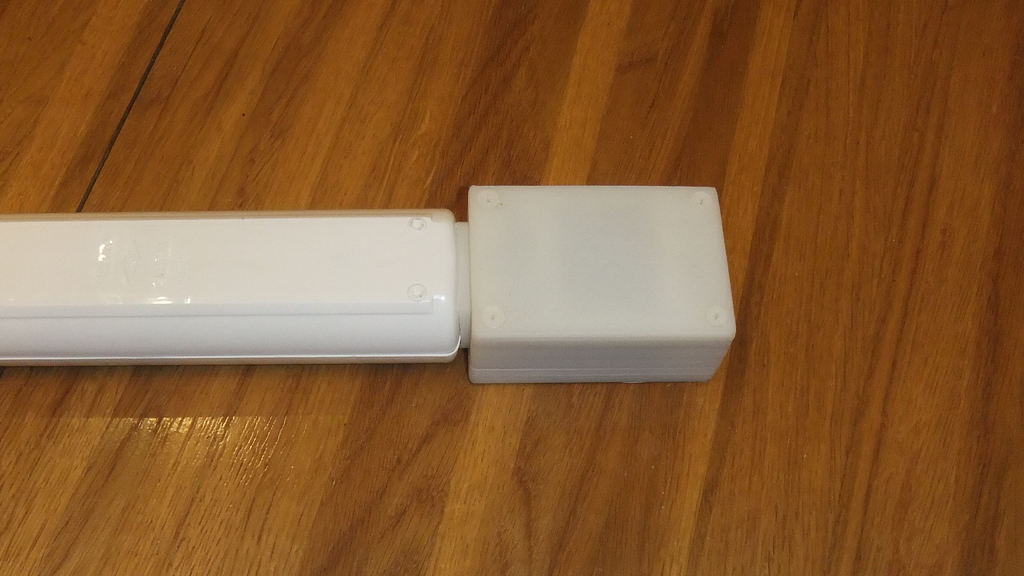
The Kicad files of the circuit can be found in the power_strip_kicad folder at. Step 4: Preparing the Power Strips. Modifying the power strips is pretty straight forward. As can be seen both the power strips have switches for each socket. The IoT power strip project also uses the same node-red and MQTT instances. Step 11: Suggestions for
